Online gas-in-oil measurement sensor Hydrocal 1008, a system with 8 outputs for measuring:
- H2 Hydrogen
- CO Carbon Monoxide
- CO2 Carbon Dioxide
- CH4 Methane
- C2H2 Acetylene
- C2H4 Ethylene
- C2H6 Ethane
- H2O Moisture
Online gas-in-oil measurement sensor Hydrocal 1008, a system with 8 outputs for measuring:
The HYDROCAL 1008 is a permanently installed multi-gas-in-oil analysis system with transformer monitoring functions.
It individually measures the key gases dissolved in transformer oil, such as:
It additionally measures Moisture in Oil (H2O).
As Hydrogen (H2) is involved in nearly every fault of the insulation system of power transformers and Carbon Monoxide (CO) is a sign of involvement of the cellulosic / paper insulation, the presence and increase of Acetylene (C2H2) and Ethylene (C2H4) further classifies the nature of a fault as overheating, partial discharge or high energy arcing.
The device can serve as a compact transformer monitoring system by the integration/connection of other sensors present on a transformer via its optional analog inputs:
It is further equipped with digital outputs for the transmission of alarms or the execution of control functions (e.g. control of a cooling system of a transformer):
The Hydrocal 1008 can be used as a complete monitoring system for the condition of the transformer. The main monitoring options are listed below:
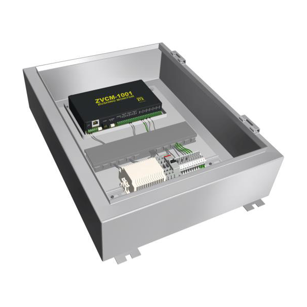
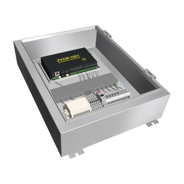
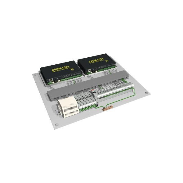
The Bushing Monitoring System simultaneously monitor’s the bushing leakage current of 2, three-phase groups of bushings. The Bushing Monitoring system incorporates three different measurement modes on each tested component to provide accurate Power Factor and Capacitance values to evaluate the condition of bushing insulation. The measurement modes are:
Phase comparison: Compares the power factor of the tested component with another tested component energised with the same phase voltage
Sum of three current tests: Measures the imbalance current from the summation of A, B and C phase currents from three tested components such as the three HV or LV bushings on the transformer
Adjacent phase reference test: Compares the power factor of the tested components with other phase components on the same equipment
The bushing sensors/adapters are connected to the capacitor taps designed for all bushings to allow measurement of the leakage current up to 140 mA. The adapters are designed for bushings with grounded and undergrounded capacitor taps. The adapter is designed to prevent voltage from developing on the equipment should the sensor become disconnected from Bushing Monitoring System.
Different bushing sensor configurations are possible:
Configuration with 3, 6, 9 or 12 bushing sensors possible.
| Technical Data | |
| Optional nominal voltages of auxiliary supply | 120 V -20% +15% AC 50/60 Hz |
| Power consumption | Max. 600 VA |
| Housing | Alluminum |
| Dimensions | W 263 x H 263 x D 327.5 mm |
| Weight | approx. 15 kg |
| Operation temperature (ambient) | -55 °C ... +55 °C (below -10°C display function locked) |
| Oil temperature (in the transformer) | -20 °C ... +90 °C |
| Storage temperature (ambient) | -20 °C ... +65 °C |
| Oil pressure | up to 800 kPa (negative pressure allowed) |
| Connection to valve | G 1½" DIN ISO 228-1 1½” NPT ANSI B 1.20.1 |
| Safety | CE certified |
| Insulation protection | IEC 61010-1:2002 |
| Degree of protection | IP-55 |
| Analog outputs | ||
| Type | Range | Default concentration (Free assignment) |
| 1 Current DC | 0/4 ... 20 mA DC | Hydrogen H2 |
| 1 Current DC | 0/4 ... 20 mA DC | Acetylene C2H2 |
| 1 Current DC | 0/4 ... 20 mA DC | Ethylene C2H4 |
| 1 Current DC | 0/4 ... 20 mA DC | Carbon Monoxide CO |
| 1 Current DC | 0/4 ... 20 mA DC | Moisture H20 |
| 1 Current DC | 0/4 ... 20 mA DC | Carbon Dioxide CO2 |
| 1 Current DC | 0/4 ... 20 mA DC | Ethane C2H6 |
| 1 Current DC | 0/4 ... 20 mA DC | Methane CH4 |
| Digital outputs | ||
| Type | Control voltage | Max. Switching capacity (Free assignment) |
| 8 relè | 12 V DC | 220 V DC / V AC / 2A / 60 W |
| Communication |
| RS 485 (proprietary or MODBUS® RTU/ASCII protocol) |
ETHERNET 10/100 Mbit/s copper-wired / RJ 45 or fibre-optical / SC Duplex (proprietary or MODBUS® TCP protocol) |
| 2G/3G modem with external adhesive antenna (Option) (proprietary protocol) |
| DNP3 serial modem (Option) |
| IEC 61850 modem (Option) |


There are no articles in the shopping cart